Facilities ![]() Shock Tube
Shock Tube
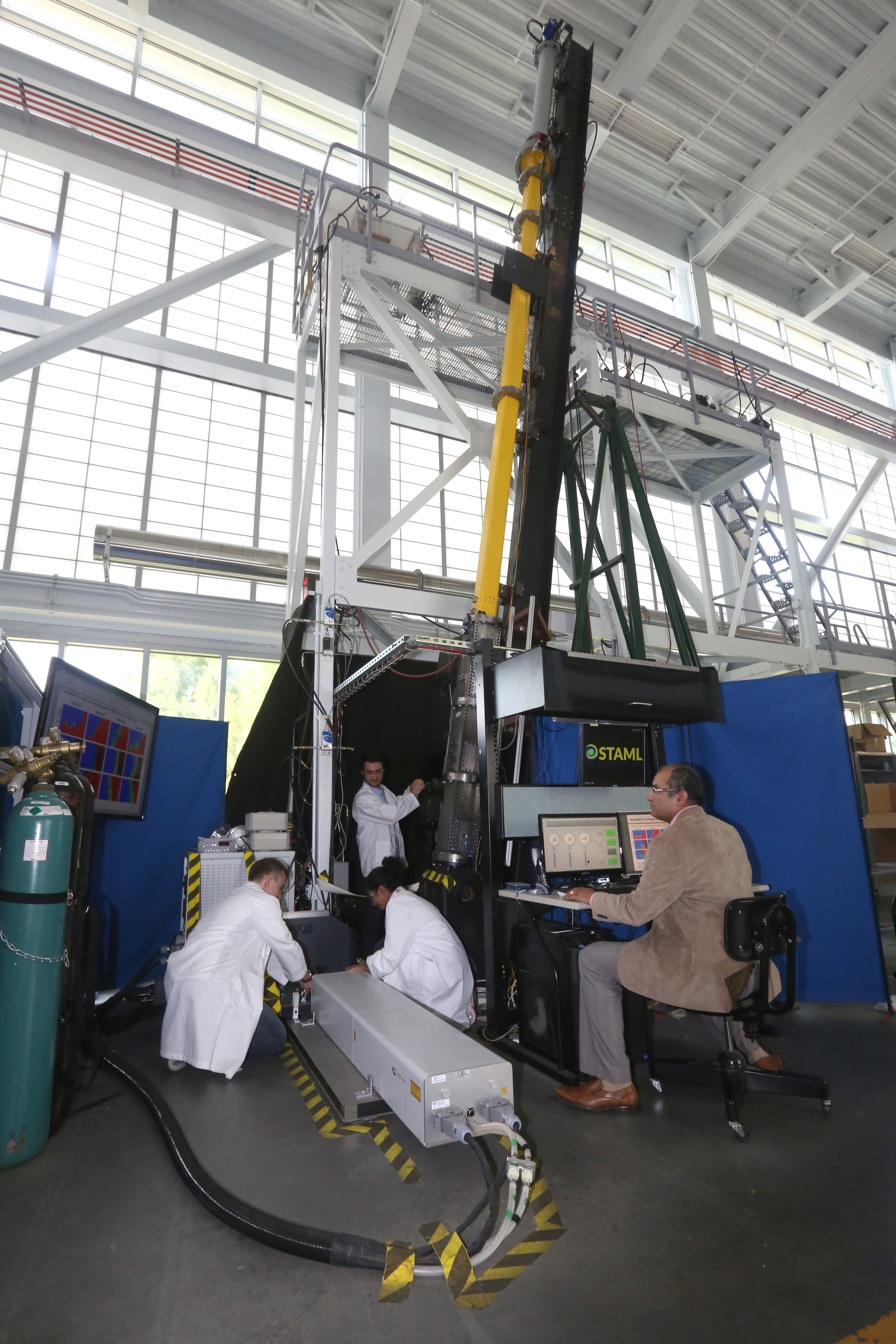 The Georgia Tech shock tube was designed for inclined interface shock-driven, formally known as Richtmyer-Meshkov (RM), experiments and was completed in May of 2012. It is approximately 9 meters long with a 1.7m driver and weighs about 4000lbs. The test section has a square cross section that is 11.43cm on a side. The modular design of the test section allows it to be reconfigured for different experiments. It is capable of inclination angles from 0 to 90 degrees and can send incident shock waves at up to Mach 3.0 into atmospheric air. The shock waves are generated when a diaphragm separating the high-pressure driver section from the atmospheric-pressure driven section is burst by means of a sudden increase in driver pressure supplied by a fast acting boost valve. The Diaphragm is held in place by a hydraulic diaphragm loader which clamps the diaphragm in place with over 50,000lbf and allows for diaphragms to be replaced in under 5 minutes.
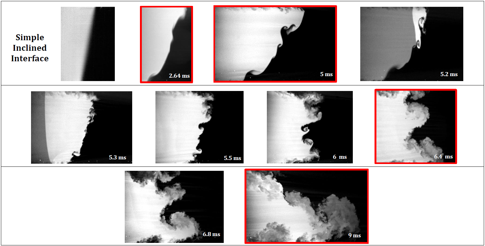
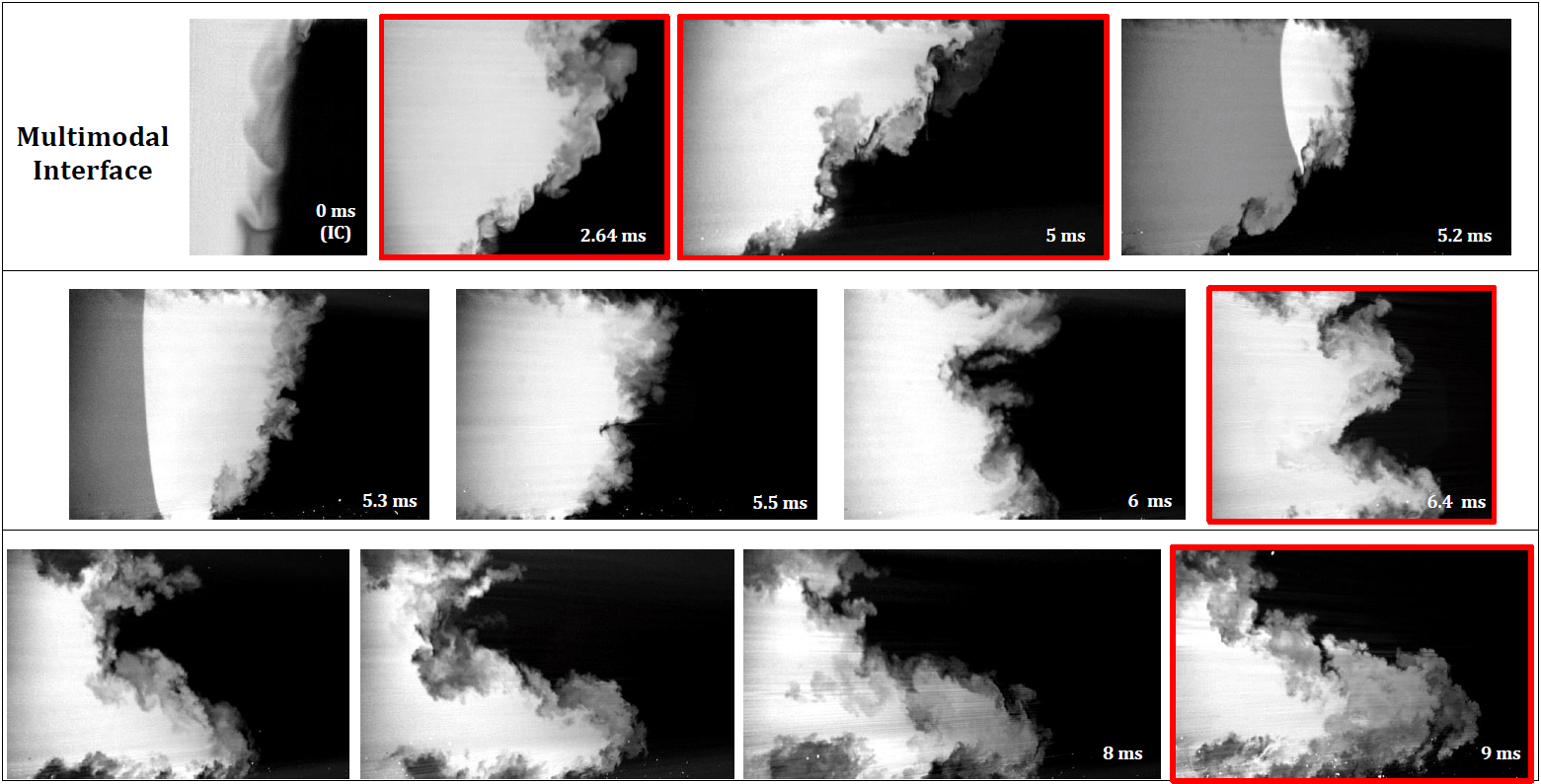
 An interface consisting of a light gas such as nitrogen resting over a heavy gas like carbon dioxide is created in the test section by co-flowing the light and heavy gases from the top and bottom of the tube and allowing them to vent to the atmosphere at a plane in the test section. This interface is parallel to the ground, but oblique to the planar shock wave because the entire tube is inclined. The oblique angle between the interface and the shock front is the source of the RM instability. The test section has 8 locations where windows can be installed to allow images of the evolving flow field to be taken. The images are acquired using laser sheets to illuminate the interface. One or more optical diagnostics can be employed including planar laser induced fluorescence, particle imaging velocimetry, and mie scattering. A reconfiguration of the test section allows Schleiren images to be taken as well. The images are acquired using 2 high quantum efficiency PLIF cameras, 2 high resolution PIV cameras or a fast framing video camera capable of over one million frames per second. The triggering of the cameras and control of the shock tube is performed by a national instruments system connected to solenoid valves, relays, thermocouples, static pressure transducers, and dynamic piezoelectric pressure transducers. Two example series of PLIF images can be seen below.
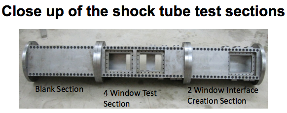
To meet the viewing requirements multiple windows were used which have overlapping fields of view, and provide up to a 0.6m continuous field of view. Laser optical access is provided by a small slit window at the end of the tube which can withstand the high loads resulting from reshock. The primary interface perturbation will be created by inclining the shock tube, using gravity to set up a density perturbation which is misaligned with the impending shock wave. The interface is kept sharp by co-flowing gasses from above and below and providing narrow, pressure-controlled exit ports along the entire length of the interface sides. Three sets of ports are provided initially for 30, 45 and 60 degree inclinations, but may be rearranged for additional inclination angles. These ports are sealed so that suction may be applied to the tube to control the interface diffusion. The Georgia Tech shock tube facility has been built with flexibility in mind, making it capable of performing many different experiments by simply reconfiguring the sections. With multiple viewing sections, the interface can be made visible to laser diagnostics at early and late times for any experimental conditions. This facility is also capable of creating two interfaces in an experiment, such as helium over air over SF6. . Each section can also be disassembled to allow new geometries to be created such as a converging or diverging section.
 Instrumentation and Measurement Equipment:
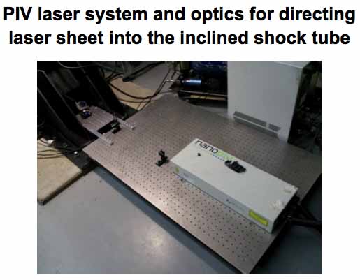
Operation and timing of the shock tube is controlled using a high speed (2MHz) National Instruments system in conjunction with eight dynamic pressure transducers to trigger the optical measurement systems. These optical measurements will consist of PLIF and PIV measurement systems. The systems will provide simultaneous density and velocity field measurements. The simultaneous Stereo PIV/PLIF system consists of multiple lasers which can emit light at both 266nm and 532nm wavelengths, two progressive scan CCD cameras for PIV, and two PLIF cameras and light sheet optics. A 266nm light sheet will be used for PLIF in conjunction with appropriate light filters for the PLIF cameras to capture the fluorescent signal. Additionally, a 532nm light sheet will be used for PIV to measure velocities by statistical correlation of the seeded particle position between two frames separated by a few microseconds. The stereo PIV system consists of two PIV cameras positioned at an angle to the flow, enabling the measurement of the out-of-plane velocity component, are equipped with 532nm light filters to catch the signal only from the PIV particles. Another laser, which can produce 532 nm light at 120mJ per pulse, can be used to make PIV measurements at some other location for the same experiment. Both of the lasers are equally powerful at 532nm and the PLIF laser can provide a 120mJ pulse at 266nm. Additional images of the facility can be seen in the sidebar to the right.
Instrumentation and Measurement Equipment:
Operation and timing of the shock tube is controlled using a high speed (2MHz) National Instruments system in conjunction with eight dynamic pressure transducers to trigger the optical measurement systems. These optical measurements will consist of PLIF and PIV measurement systems. The systems will provide simultaneous density and velocity field measurements. The simultaneous Stereo PIV/PLIF system consists of multiple lasers which can emit light at both 266nm and 532nm wavelengths, two progressive scan CCD cameras for PIV, and two PLIF cameras and light sheet optics. A 266nm light sheet will be used for PLIF in conjunction with appropriate light filters for the PLIF cameras to capture the fluorescent signal. Additionally, a 532nm light sheet will be used for PIV to measure velocities by statistical correlation of the seeded particle position between two frames separated by a few microseconds. The stereo PIV system consists of two PIV cameras positioned at an angle to the flow, enabling the measurement of the out-of-plane velocity component, are equipped with 532nm light filters to catch the signal only from the PIV particles. Another laser, which can produce 532 nm light at 120mJ per pulse, can be used to make PIV measurements at some other location for the same experiment. Both of the lasers are equally powerful at 532nm and the PLIF laser can provide a 120mJ pulse at 266nm. Additional images of the facility can be seen in the sidebar to the right.